Lowcar Devices
Runtime supports devices that implement the lowcar protocol. This section contains an assortment of physical devices and "virtual" devices, along with their parameters and a description of each device.
These devices are part of the students toolkit. I would recommend playing around with them when you get the chance. Not only is good to "visualize" the parameters, it's also really fun :)

| Name | type | Readable | Writeable |
|---|---|---|---|
| RUNTIME | INT | 1 | 0 |
| SHEPHERD | FLOAT | 1 | 0 |
| DAWN | BOOL | 1 | 0 |
| DEVOPS | INT | 1 | 0 |
| ATLAS | FLOAT | 1 | 0 |
| INFRA | BOOL | 1 | 0 |
| SENS | INT | 0 | 1 |
| PDB | FLOAT | 0 | 1 |
| MECH | BOOL | 0 | 1 |
| CPR | INT | 0 | 1 |
| EDU | FLOAT | 0 | 1 |
| EXEC | BOOL | 0 | 1 |
| PIEF | INT | 1 | 1 |
| FUNTIME | FLOAT | 1 | 1 |
| SHEEP | BOOL | 1 | 1 |
| DUSK | INT | 1 | 1 |
This thicc boi is as the name implies, a dummy device with no advanced functionality. This only really used for testing purposes on a bare physical Arduino micro. It allows us to experiment and test all the possible parameters and their functionalities. It allows us to simulate how a lowcar device may interact with dev_handler. It has a decent amount of read-only, write-only, and readable/writeable params based on the different runtime teams and a couple of easter eggs ;)
| Name | type | Readable | Writeable |
|---|---|---|---|
| switch0 | BOOL | 1 | 0 |
| switch1 | BOOL | 1 | 0 |
| switch2 | BOOL | 1 | 0 |
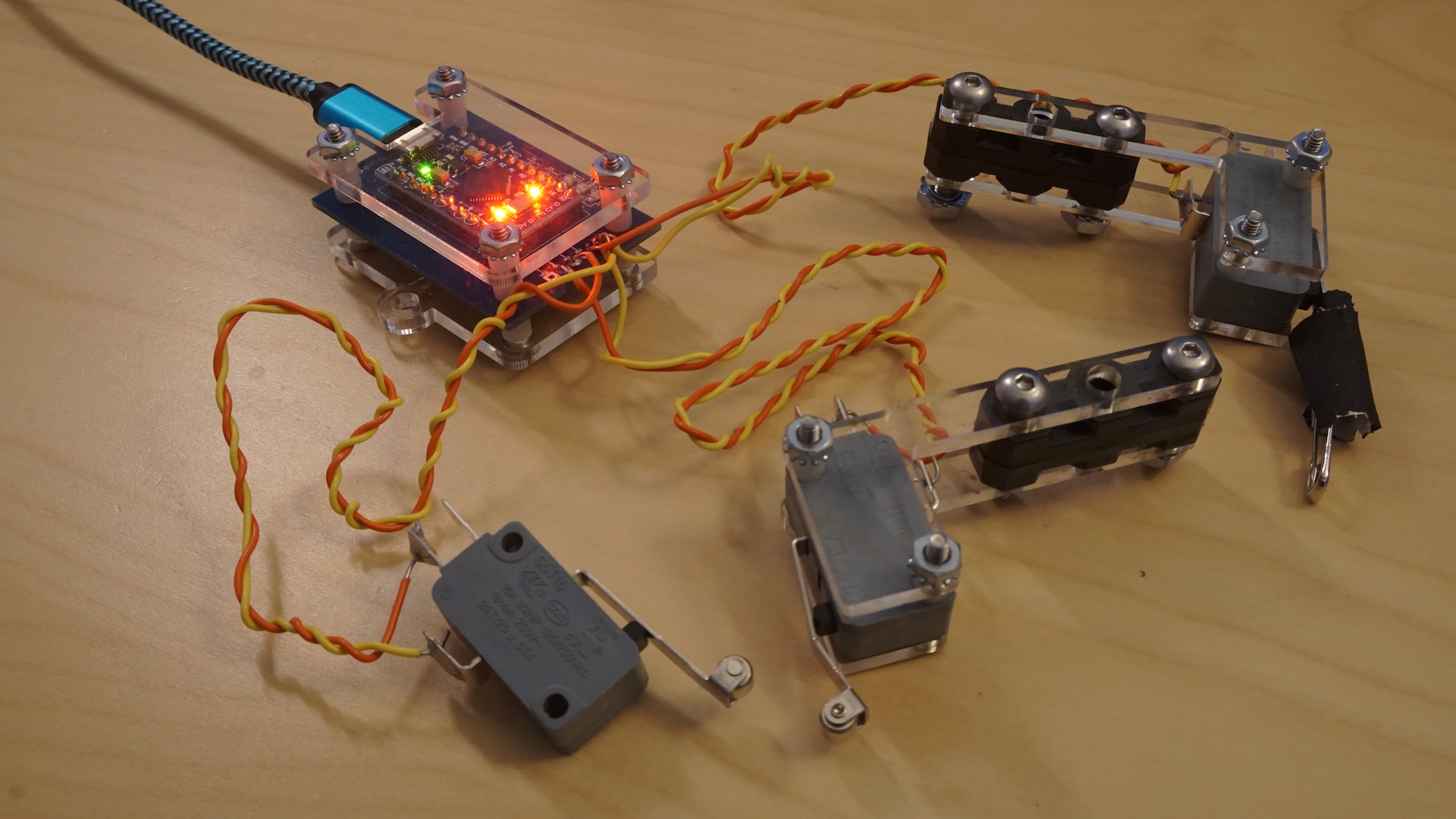
A limit switch is a device wired to three switches. These switches, SWITCH0, SWITCH1, and SWITCH1, each have a metal actuator attached to them. The original use of a limit switch is as the name implies, to limit an object from going past a certain endpoint. Unlike the original use, however, we allow students to dictate what action the robot should perform if the actuator was pressed against. Students also have free range to put the three switches wherever they please.
Each switch has a boolean, read-only value that changes depending on whether the actuator was pressed against. This value can be read from the pin that the corresponding limit switch is attached too.
| Name | type | Readable | Writeable |
|---|---|---|---|
| left | FLOAT | 1 | 0 |
| center | FLOAT | 1 | 0 |
| right | FLOAT | 1 | 0 |
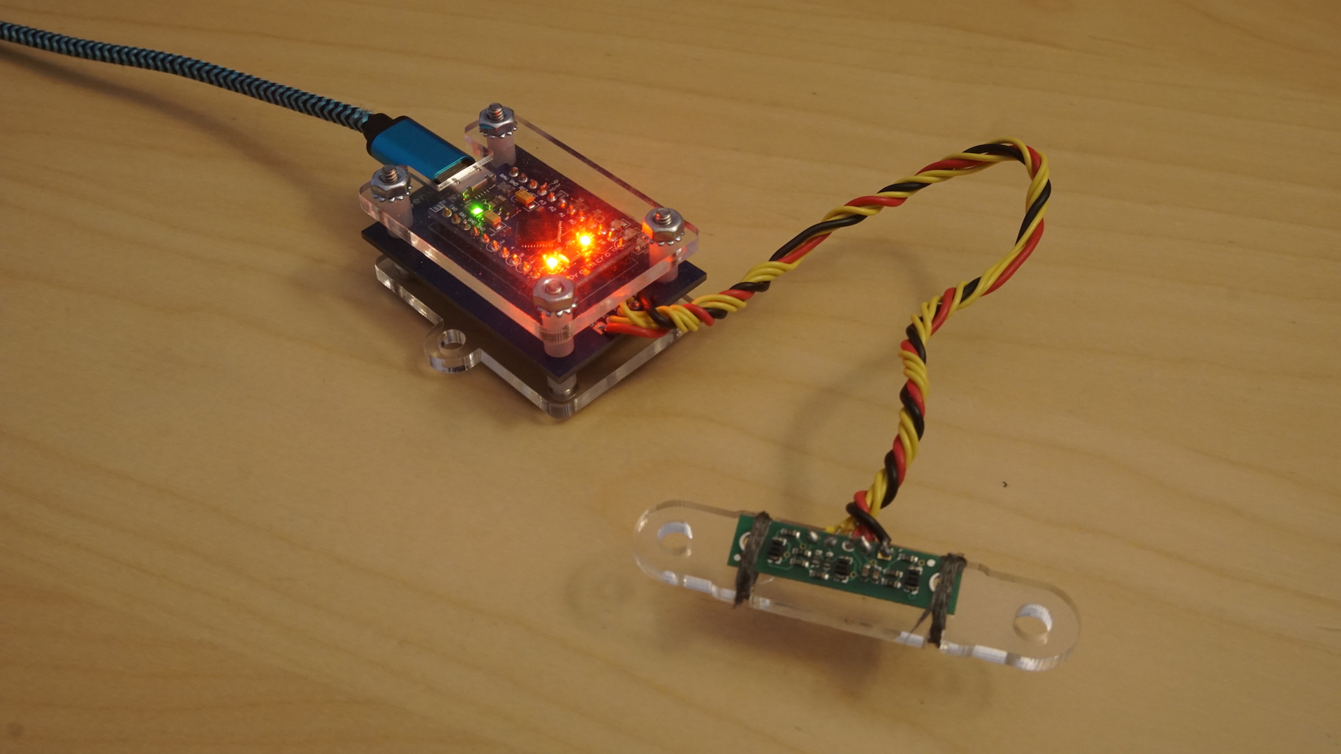
A line follower is an active sensor that shines an infrared light down and reads the reflection of said infrared light. There are three sensors attached to the bottom of the limit switch to read the reflected light. Using the reflected light, the line follower can send how much light was reflected in three main areas relative to the infrared light: the left to it, the center, or middle, of it, and the right of it. The reflected light values are represented as floats with a range between 0 and 1, where 0 represents no light reflected and 1 represents all the infrared light being reflected. The device then takes that value from the sensor, and subtracts it from 1 to get the total amount of light reflected.
Each sensor returns a value and by getting the value from the pin associated with the sensor, the students can make calculated moves based on what the line follower is reading.
| Name | type | Readable | Writeable |
|---|---|---|---|
| is_unsafe | BOOL | 1 | 0 |
| calibrated | BOOL | 1 | 0 |
| v_cell1 | FLOAT | 1 | 0 |
| v_cell2 | FLOAT | 1 | 0 |
| v_cell3 | FLOAT | 1 | 0 |
| v_batt | FLOAT | 1 | 0 |
| dv_cell2 | FLOAT | 1 | 0 |
| dv_cell3 | FLOAT | 1 | 0 |
Have you ever thought about how your robot’s battery is doing? Well guess what, us too! With the battery buzzer, students are able to plug their battery into this device and get readings on how their device is doing and whether its safe to continue usage. The battery buzzer has 8 parameters.
The first param is is_unsafe. This param is mostly determined by the function handle_safety() which in turn, calls compute_safety(). compute_safety() checks for 4 cases of unsafe conditions in the battery based on the most recent battery readings. These include:
- Being below the minimum required voltage values
- Being above the maximum voltage value
- Imbalanced cell voltages
- The battery is occasionally, but still often, dipping under the minimum threshold and then coming back up to the “safe” threshold.
If the battery falls under one of these cases, a flag is set depending on which case along with an unsafe tag. So as an example, if we are below minimum values, an “under_volt” flag and “is_unsafe” variable are set to true. After running these checks, we then buzz the battery if is_unsafe is true.
The other boolean variable in battery buzzer is calibrated. This checks to see if the buzzer is calibrated in relation to the battery. Without proper calibration, the voltage readings from the battery buzzer pins may be inaccurate. It does this by checking a calibration array that gets initialized to default values from pdb_defs.h. Upon checking, if these values match the default values, then it is safe to assume it hasn’t been calibrated yet and set the bool value to false.
The calibration array is modified in the function handle_calibration(), which is ran pretty often in a loop and checks to see if a student hit the calibration function. If hit, we check to see if the calibration array is default values, and if so, we calculate the vref of each pin and overwrite them in the calibration array. If the calibration array is set to anything other than default values, then we clear it and recalculate the vref values in the calibration array.
The next three parameters in a battery buzzer are the v_cells, v_cell1, v_cell2, and v_cell3. These are used to calculate whether the battery is safe for use or should be replaced. The values are calculated at least twice a second. In the function measure_cells(), we read from the resistor values from each cell corresponding to their analog. We then use these values to calculate the voltage of each cell. The dv_cell2 and dv_cell3 parameters are also updated in the same calculation, since its based on the voltage of the cells.
Lastly, we have the v_batt parameter which is essentially just the v_cell3 parameter and represents how much voltage is in the battery as a whole.
| Name | type | Readable | Writeable |
|---|---|---|---|
| servo0 | FLOAT | 1 | 1 |
| servo1 | FLOAT | 1 | 1 |
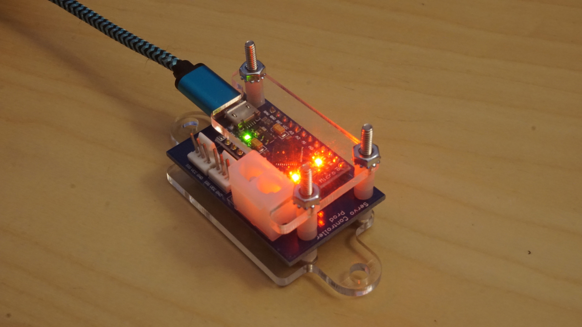
A servo controller is a device that controls the movement of two servo motors it is attached too. Servos are small mechanical devices that allow students to make precise movements without the size and weight of a regular motor. The tradeoff here is that it has significantly less power than a motor and has a smaller range of motion.
Both servos, servo0 and servo1, serve as parameters to the servo controller and are readable and writeable parameters. Upon initialization, the servo controller resets the servos to a default starting position and sets the values in the position array to 0. The servo also isn’t technically connected to a pin on the servo controller until the first write to that servo. If already attached or after being attached, the servo controller then calculates how much to move the servo by depending on its starting position and the input that was fed to the servo controller. Each servo has a range of motion of 180 degrees. We can also read each servo’s current positions by grabbing it from the positions array. Each servo’s position is stored as a float.
| Name | type | Readable | Writeable |
|---|---|---|---|
| duty_cycle | FLOAT | 1 | 1 |
| motor_current | FLOAT | 1 | 0 |
| deadband | FLOAT | 1 | 1 |
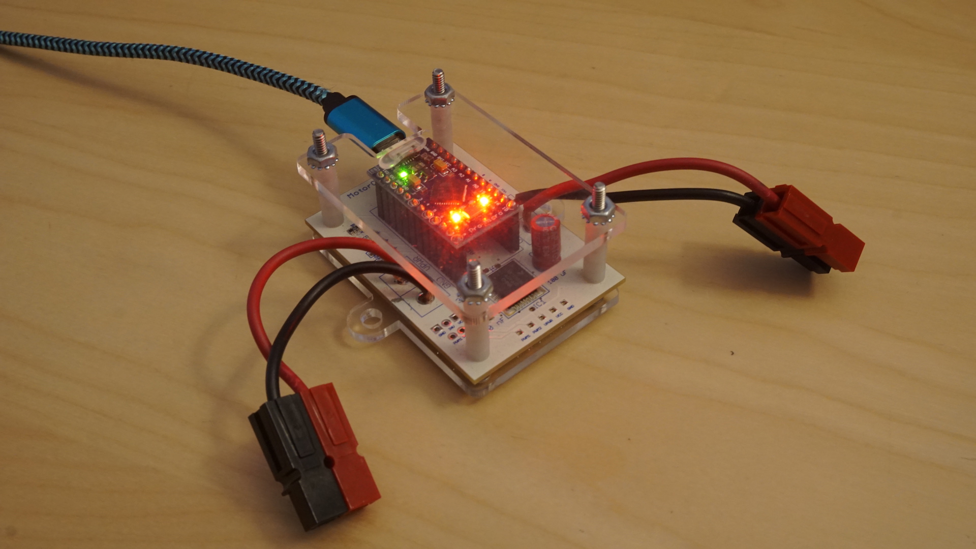
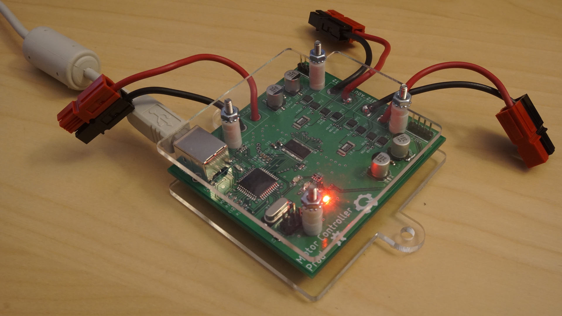
Ah yes the beautiful polar bear. Quite a majestic device really. The polar bear is known as a motor controller. Essentially, a motor controller manages the movement speed of the motor it is attached to. This reliable beauty has three parameters.
The first one is duty_cycle, a float value which essentially dictates how powerful the motor should be and in what direction. Students are allowed to modify this to be a value between -1 and 1, where 1 is max power in a clockwise direction and -1 is power in a counterclockwise direction.
The next parameter is motorcurrent, a read only float that stands for the current flowing through the motor. This is read from the “FEEDBACK” pin.
Lastly, we have the deadband parameter, which is a float used to create a limit that a parameter must meet. Deadbands are typically used to prevent oscillation in a circuit. So if the change to some value, such as the duty_cycle, is small enough to be less than deadband, then the motor controller ignores that change. For example, if upon initialization, deadband is set to 0.05, and duty_cycle is set to 0.04, then no action will be taken by the motor controller. If duty_cycle is then changed to 0.07, then the motor controller will handle that input.
Other functionalities of the motor controller is that it has LEDs that light up depending on the motion. The green LED lights up in forward movement, yellow in backward, and red if stopped. The motor controller also calculates how much to accelerate by manipulating the pins in the motor.
WAITING ON ELECTRICAL FOR EXACT PARAMETERS
The distance sensor is another active sensor in the student’s toolkit. The sensor does as is described, it detects the distance between the sensor and an object in front of it. The range of distance it reads is from 0cm to 500 cm. The distance sensor is, in fact, two sensors on this one device.
The first sensor is an ultrasonic sensor. This sensor utilizes ultrasonic waves and their reflections to detect how far away an object is. It is stored as a read only long. The ultrasonic sensor can pick up the distance of objects from about 500cm away. One drawback about the ultrasonic sensor is it can get “fuzzy” at closer ranges, i.e. about 5cm. However, our brilliant staff from electrical have come up with a solution!
When the sensor is too close to an object, the IR sensor kicks in to notify the sensor that there is an object in front of it. The drawback for the IR sensor is it’s only a Boolean value. It cannot say how far an object is, only if its close. The IR sensor has a range of about 30 cm.
| Name | type | Readable | Writeable | Default Value |
|---|---|---|---|---|
| velocity_a | FLOAT | 1 | 1 | 0.0 |
| deadband_a | FLOAT | 1 | 1 | 0.05 |
| invert_a | BOOL | 1 | 1 | False |
| pid_enabled_a | BOOL | 1 | 1 | True |
| pid_kp_a | FLOAT | 1 | 1 | 0.05 |
| pid_ki_a | FLOAT | 1 | 1 | 0.035 |
| pid_kd_a | FLOAT | 1 | 1 | 0.0 |
| enc_a | INT | 1 | 1 | 0 |
| velocity_b | FLOAT | 1 | 1 | 0.0 |
| deadband_b | FLOAT | 1 | 1 | 0.05 |
| invert_b | BOOL | 1 | 1 | False |
| pid_enabled_b | BOOL | 1 | 1 | True |
| pid_kp_b | FLOAT | 1 | 1 | 0.05 |
| pid_ki_b | FLOAT | 1 | 1 | 0.035 |
| pid_kd_b | FLOAT | 1 | 1 | 0.0 |
| enc_b | INT | 1 | 1 | 0 |
KoalaBear is the newest motor controller and the one that will be used from here on out. It has the same basic functionality as the PolarBear, it controls the motor’s speed, but is more advanced and has greater functionality than its predecessor. One of the two big changes is that a single KoalaBear can reign supremacy over two motors as opposed to the one like with a PolarBear. Because of this change, the KoalaBear comes with 16 parameters, making it a thicc device. 8 of the parameters are dedicated to “motor A” and the other 8 are dedicated to “motor b.”
The first two parameters are similar like PolarBear’s parameters: velocity and deadband. velocity is kind of like duty_cycle on the PolarBears. It is the speed the students want the motor to operate at. It is a float ranging from -1 to 1. deadband is a threshold that velocity must pass before any changes are made to the motor. It is a float between 0 and 1. For a little more detail and example on how these parameters work together, see the section on Polar Bear devices.
The third parameter, invert, allows the student to run the motor in the opposite direction as specified. If when the student plugs in the motor, they realize that a velocity of 1.0 corresponds to the opposite of the preferred direction of positive velocities for the motor, they can set invert to True and cause the velocity of 1.0 to correspond to the preferred direction for positive velocities.
Before moving on to the next set of parameters, we must first talk about the other great change with KoalaBear. Each KoalaBear has a built in encoder that allows us to utilize PID control! An encoder is basically a device that allows us to translate the motor’s movements into actual distance values. Each motor's encoder is accessed with two pins. The outputs of both pins for an encoder are in the form of square waves at the frequency of the motor’s rotation; they are slightly offset from each other. By examining the value of one pin relative to another pin when one of the pins encounters a rising edge, we can determine which direction the motor is rotating. If the voltage of the second pin is 0, then its spinning clockwise, but if it's 5 V, it's counterclockwise. This check is triggered after each rising edge of the encoder related to either motor A or motor B. With these checks, we either increment or decrement the enc_a or enc_b integer parameters depending on which motor is the moving and in which direction. With this information, we can then implement PID control.
PID, which stands for proportional integral derivative, is a control loop feedback mechanism to control variables and give the most stable outputs. Essentially, it uses its own outputs as a variable in the inputs to produce accurate outputs. It does this by trying to minimize the “error” of the system down to zero. When the system first starts up, its error to the outcome is initially high, since we haven’t achieved the desired outcome. What I mean by this, is that the closer we get the desired outcome, the more our error will decrease which will be taken into account by the system. To calculate the error, we must sum three things together: the error itself, the accumulated error, and the expected error. These three are respectively multiplied by constant weights KP, KI, and KD. These K values must be adjusted correctly so that its not overtly sensitive or lack sensitivity. For a more in-depth, cohesive explanation, check out these videos: God Tier PID explanation and PID Examples!
PID can be used for many scenarios, but in our case, we just want to make sure the motor’s drive our robot at the appropriate speed. This is only used if the flag pid_enabled is set to true for either motor. When the robot moves forward, we use the enc_a/enc_b variables as the current position to calculate the error values and the desired output. The desired output is a value between [-1,1] that will be used to tell us how much to adjust the motor controller pins by. Upon each calculation, the values that were generated in this iteration are stored into previous values for use at the next calculation. Each motor comes with its own KP, KI, and KD variables as floats to use in this calculation.
The output is then fed into the drive() function in Koalabear to set the appropriate pins at the needed positions to get the robot to move at its intended speed. To move forward, we set the pwm2 pin to 255 and move pmw1 down to the calculated number. To move backwards, we set pmw1 to 255 and the pmw2 pin to the calculated number. This device is really remarkable and really shows the might of our Electrical team!
These devices exist for testing purposes and mimic physical lowcar devices. They allow us to write a wide range of tests.
| Name | type | Readable | Writeable |
|---|---|---|---|
| GET_TIME | BOOL | 1 | 1 |
| TIMESTAMP | INT | 1 | 0 |
The TimeTestDevice is essentially a device used for performance testing. With this device, we are testing the responsiveness between a button press and the time a device receives a response from net_handler. Of course this isn’t an exact measurement but rather a best approximation.
This device has two parameters, get_time, a bool value which sets of the change in the next parameter, timestamp. timestamp is an int that takes the last 9 digits of the time in milliseconds. This is because the time is in UNIX epoch, so the later digits aren’t necessarily as important. This device returns that time stamp so we can then subtract the time of a button press to the response of the device.
| Name | type | Readable | Writeable |
|---|---|---|---|
| NUM_ACTIONS | INT | 1 | 0 |
Another virtual device that we use for testing. This device is supposed to mimic a real lowcar device for very few seconds. After those seconds, the device goes silent and doesn’t send any more packets. This is to test that lowcar properly disconnects the device from shared memory after the device goes silent.
The only parameter in this virtual device is the NUM_ACTIONS param which is essentially a counter that gets checked and incremented on each device_action. Once it passes a threshold, the device sleeps for 60 seconds, giving dev_handler more than enough time to properly handle the device.
NO PARAMETERS
A device that does literally nothing. It just sleeps. Still more active than me in any history classes sooooo :p
In all seriousness this is just to make sure that a device that doesn't send back an ACK also doesn't get connected to shared memory.
NO PARAMETERS
This device continuously sends random bytes. It does include the delimiter, 0x00, but outside of that it's just random bytes that don't really mean anything. This device is also used to make sure no communication continues between a dev_handler and a device that doesn't send an ACK.
| Name | type | Readable | Writeable |
|---|---|---|---|
| INCREASING | INT | 1 | 0 |
| DOUBLING | FLOAT | 1 | 0 |
| FLIP_FLOP | BOOL | 1 | 0 |
| MY_INT | INT | 1 | 1 |
This virtual device acts like a lowcar device with a few parameters. The three out of the four are read-only parameters and the fourth one is a readable and writeable parameter. Upon each action, the device modifies its read only parameters. Its read only params cover all possible parameters in a lowcar device, ints, floats, and bools. This device is ideally used for sanity checks to make sure that dev_handler and lowcar are both properly functioning.
| Name | type | Readable | Writeable |
|---|---|---|---|
| INCREASING_ODD | INT | 1 | 0 |
| DECREASING_ODD | INT | 1 | 0 |
| INCREASING_EVEN | INT | 1 | 0 |
| DECREASING_EVEN | INT | 1 | 0 |
| INCREASING_FLIP | INT | 1 | 0 |
| ALWAYS_LEET | INT | 1 | 0 |
| DOUBLING | FLOAT | 1 | 0 |
| DOUBLING_NEG | FLOAT | 1 | 0 |
| HALFING | FLOAT | 1 | 0 |
| HALFING_NEG | FLOAT | 1 | 0 |
| EXP_ONE_PT_ONE | FLOAT | 1 | 0 |
| EXP_ONE_PT_TWO | FLOAT | 1 | 0 |
| ALWAYS_PI | FLOAT | 1 | 0 |
| FLIP_FLOP | FLOAT | 1 | 0 |
| ALWAYS_TRUE | BOOL | 1 | 1 |
| ALWAYS_FALSE | INT | 1 | 1 |
| RED_INT | INT | 1 | 1 |
| ORANGE_INT | INT | 1 | 1 |
| GREEN_INT | INT | 1 | 1 |
| BLUE_INT | INT | 1 | 1 |
| PURPLE_INT | INT | 1 | 1 |
| RED_FLOAT | FLOAT | 1 | 1 |
| ORANGE_FLOAT | FLOAT | 1 | 1 |
| GREEN_FLOAT | FLOAT | 1 | 1 |
| BLUE_FLOAT | FLOAT | 1 | 1 |
| PURPLE_FLOAT | FLOAT | 1 | 1 |
| RED_BOOL | FLOAT | 1 | 1 |
| ORANGE_BOOL | BOOL | 1 | 1 |
| GREEN_BOOL | BOOL | 1 | 1 |
| BLUE_BOOL | BOOL | 1 | 1 |
| PURPLE_BOOL | BOOL | 1 | 1 |
| YELLOW_BOOL | BOOL | 1 | 1 |
Exactly like a SimpleTestDevice but exercises all 32 parameters. Just like SimpleTestDevice, it has an assortment of int, float, and bool values. The first 16 parameters are all read only and are changed upon each device action.
The names of the 16 read-only parameters describe what exactly is changing on each device action. The other 16 parameters are different types that the tests can write to and read from. This virtual device is used across many of our original dev_handler tests.