Creating Models
In this wiki I will describe how to create Lua and URDF models. The models generally are broken up into the following components:
- The model kinematics/dynamics, consisting of the link length, kinematic chain, and dynamic parameters like the inertial matrix, centre of mass, and link mass
- The model visualizatoin, consisting of a basic wireframe, and surface meshes
- Note that RBDL-Toolkit currently only supports
.stlfiles for meshes
- Note that RBDL-Toolkit currently only supports
- Model marker parameters, used for inverse kinematics calculations when given marker data
RBDL is capable of working with the following model files:
- Lua: Lua models are a data structure created in the Lua language. As such, Lua models are simply Lua commands that is evaluated by the Lua compiler and offers strong flexibility.
- Unified Robot Description Format (URDF): URDF models are XML-based layout commonly used in the Robot Operating System (ROS).
The first set of example can be found in ./example/pendulum_kinematic. See below for a breakdown of file.
To load the Lua model and the trajectory file into rbdl-toolkit, the command is rbdl-toolkit --model pendulum.lua --animation pendulum.csv
rod_length = 1
Since Lua is a programming language, simple assignment operations can be used to set up variables for use for the rest of the document, allowing for rapid modifications.
meshes = {
  rod1 = {
	color = { 1, 0, 0 },
	mesh_center = {0, 0, rod_length/2},
	dimensions = { 0.2, 0.2, rod_length},
	src = "unit_cube.obj"
  },
  rod2 = {
	color = { 0, 1, 0 },
	mesh_center = {0, 0, rod_length/2},
	dimensions = { 0.1, 0.1, rod_length},
	src = "unit_cube.obj"
  }
}
The meshes object denotes how to visualize the model. Regardless of mesh definition, a basic wire-frame will be inserted to denote the mesh. The below code block describes two mesh objects that will later be used in the model itself.
-
colordenotes the colour of the object in red, green, blue (RGB) order -
mesh_centerdenotes the rotation center of this mesh. If it is set to{0, 0, 0}, it will rotate around its centre.
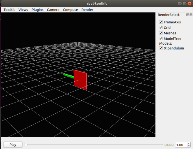
 |
|---|
| Default model from the examples |
 |
|---|
Mesh center set to {0, 0, 0}. |
-
dimensionssets the size of the mesh itself. If it is set to{0.1, 0.1, 0.1}, then it will be a 0.1 m cube.
 |
|---|
Mesh center set to { rod_length, 0.1, rod_length}. |
-
srcdenotes the source image file of the mesh. A set of default meshes can be found inmeshes\
gravity = {0, 0, -9.81},

model = {
  configuration = {
	axis_right = { 0, 1, 0 },
	axis_up =    { 0, 0, 1 },
	axis_front = { 1, 0, 0 },
  },

  },
-
gravitydenotes the direction of gravity with respect to the global frame. This is an important factor when you are using RBDL to calculate joint torque, but not important in this particular instance because the dynamic parameters are not incorporated yet. -
configurationdenotes how the global frame is being visualized, and does not affect RBDL itself. This parameter is generated in the form of a rotation matrix,R_G_Mmapping from the OpenGL frame to the model's room frame. The default layout of OpenGL is{x, y, z} = {right, up, front}. That is, if you do not want any rotation between the OpenGL visualization and RBDL, the configuration matrix would be identity, and should be set to:
  configuration = {
	axis_right = { 1, 0, 0 },
	axis_up =    { 0, 1, 0 },
	axis_front = { 0, 0, 1 },
  },
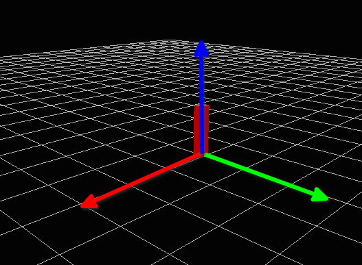
- In the default camera view (
Toolkit > Settings > CameraOptions, position at<6,3,6>and view_center at-4. 34917, -1.85781, -4.63835), then the axis directions are denoted as below:
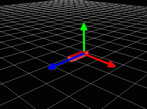 |
|---|
axis_right, axis_up, and axis_front (ie OpenGL XYZ), denoted as RGB, and matches up with RBDL XYZ. |
- If instead, you want Z axis to be up, a
roty(-90)*rotx(-90)rotation can be implemented as the rotation matrix. This results in:
configuration = {
axis_right = { 0, 1, 0 },
axis_up =    { 0, 0, 1 },
axis_front = { 1, 0, 0 },
},
 |
|---|
axis_right, axis_up, and axis_front (ie OpenGL XYZ) now corresponds to YZX. |
  frames = {
	{
	  name = "segment1",
	  parent = "ROOT",
	  visuals = { meshes.rod1 },
	  joint = {{ 1, 0, 0, 0, 0, 0 }},
	  joint_frame = {
		E = {{1, 0, 0}, {0, 1, 0}, {0, 0, 1}}
	  }
	},
	{
	  name = "segment2",
	  parent = "segment1",
	  visuals = { meshes.rod2 },
	  joint = {{ 1, 0, 0, 0, 0, 0 }},
	  joint_frame = {
		r = { 0, 0, rod_length },
		E = {{1, 0, 0}, {0, 1, 0}, {0, 0, 1}}
	  }
	}
  }
}
-
framesdenote the individual frames that make up the model tree. Each frame require the following elements:-
name, an unique name is required for each frame -
parent, the frame that this frame is attached to. The world frame is namedROOT. -
visualsdenotes the mesh that should be loaded. In this example, it refers to themeshesobject defined earlier. Note that you can chain meshes together by adding a comma:visuals = {meshes.rod1, meshes.joint_sph}for example, if there there is ajoint_sphdefined that you want at the end of this link. -
jointdenote the axes of rotation, in the order of the local frame rotation XYZ, then translation XYZ.- Multiple joints can be defined by concatination. A 3 DOF XYZ Euler joint would look like
joint = {{ 1, 0, 0, 0, 0, 0 }, { 0, 1, 0, 0, 0, 0 }, { 0, 0, 1, 0, 0, 0 }}
- Multiple joints can be defined by concatination. A 3 DOF XYZ Euler joint would look like
-
joint_framedenotes the attachment site of the frame with respect to the parent frame.-
rdenotes the translational offset. Forsegment1, no offset is set. Forsegment2, the link starts atrod_lengthaway from the parent frame. If unset, this is{0, 0, 0}. -
Edenotes the rotation matrix offset from the parent frame. If unset, this is identity{1, 0, 0}, {0, 1, 0}, {0, 0, 1}.
-
-
 |
|---|
r is set to rod_length*2 here. |
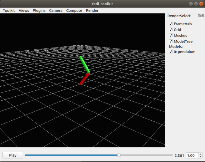
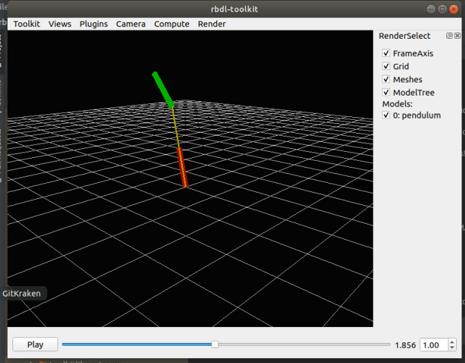
 |
|---|
| Pendulum animating. |
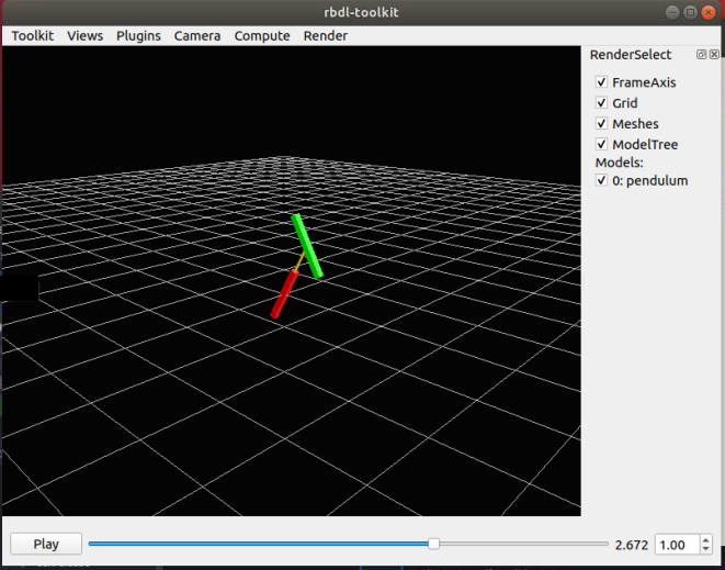
 |
|---|
| Pendulum animating after modifying the second link attachment offset and orientation: ```r = { 0., 0., -rod_length*2 |
| }, E = {{1, 0, 0}, {0, 0, -1}, {0, 1, 0}}``` |
return model
Since the Lua model is basically running a code snippet, the model must be returned.
To load the URDF model and the trajectory file into rbdl-toolkit, the command is rbdl-toolkit --model pendulum.lua --animation pendulum.csv
<?xml version="1.0" encoding="utf-8"?>
<robot name="pendulum">
	<material name="red">
		<color rgba="1 0 0 1"/>
	</material>
	<material name="green">
		<color rgba="0 1 0 1"/>
	</material>
This text sets up the XML, as well as define some variable names.
	<link name="root">
	</link>

	<link name="segment1">
		<visual>
			<geometry>
				<box size="0.2 0.2 1"/>
			</geometry>
			<origin rpy="0 0 0" xyz="0 0 0.5"/>
			<material name="red"/>
		</visual>
	</link>

	<link name="segment2">
		<visual>
			<geometry>
				<box size="0.1 0.1 1"/>
			</geometry>
			<origin rpy="0 0 0" xyz="0 0 0.5"/>
			<material name="green"/>
		</visual>
	</link>
In URDF, the linkages and the joints are defined separately. Here, each link's visual characterstics are defined.
	<joint name="roottoseg1" type="revolute">
		<axis xyz="1 0 0"/>
		<parent link="root"/>
		<child link="segment1"/>
	</joint>

	<joint name="seg1toseg2" type="revolute">
		<origin xyz="0 0 1"/>
		<axis xyz="1 0 0"/>
		<parent link="segment1"/>
		<child link="segment2"/>
	</joint>
</robot>