Commands
The graphics processor firmware uses two I/O ports for commands and data.
- Port 40H is used to send commands.
- Port 41H is used to send data bytes.
The following commands are implemented in the current firmware.
00H - Set Video Mode
Resets the video card and sets the selected mode.
The first byte sent to the data port selects the video mode:
- 00H - Mode 1 = 320x240 (40x30 Tiles)
- 01H - Mode 2 = 256x192 (32x24 Tiles)
- 02H - Mode 3 = 256x224 (32x28 Tiles)
- 03H - Mode 4 = 320x240 (Bitmap 3BPP)
- 04H - Mode 5 = 256x192 (Bitmap 4BPP)
- 05H - Mode 6 = 256x224 (Bitmap 4BPP)
        LD   A,00H
        OUT  (40H),A
        LD   A,01H      ; Mode 2 256x192
        OUT  (40H),A
        XOR  A          ; Overlay disabled
        OUT  (40H),A
        OUT  (40H),A
Tile modes (00H-02H) can specify additional flags by ORing the following values to the selected video mode:
- 80H - Doubles the horziontal video ram tiles
- 40H - Doubles the vertical video ram tiles
        LD   A,00H
        OUT  (40H),A
        LD   A,81H      ; Mode 2 256x192 with double horizontal video ram tiles (64x24)
        OUT  (40H),A
        XOR  A          ; Overlay disabled
        OUT  (40H),A
        OUT  (40H),A
The second byte sent to the data port enables the top overlay rows display. Bits 3-0 defines the number of rows, bits 4-7 defines the starting row from top. A value of 00h disables the top overlay display.
The third byte sent to the data port enables the bottom overlay rows display. Bits 3-0 defines the number of rows, bits 4-7 defines the starting row from bottom. A value of 00h disables the bottom overlay display.
        LD   A,00H
        OUT  (40H),A
        LD   A,00H      ; Mode 1 320x240
        OUT  (40H),A
        LD   A,12H      ; Display 2 overlay rows starting from row 1
        OUT  (40H),A
        LD   A,22H      ; Display 2 overlay rows starting from row 26
        OUT  (40H),A
Bitmap modes (03H-05H) can't display overlay rows and these bytes must be set to 0.
The following commands can be used when the tile graphics modes are selected.
03H - Set orizontal scroll position
Sets the number of pixels to scroll the screen in the horizontal direction.
The low order byte and the high order byte of the 16 bit pixels count needs to be sent to the data port. Valid values depends on the selected video mode and flags:
+------+-------|------+-------|------+-------+------+-------+
| Mode | Range | Mode | Range | Mode | Range | Mode | Range |
|------+-------|------+-------|------+-------|------+-------|
|  00H | 0-319 |  40H | 0-319 |  80H | 0-639 |  C0H | 0-639 |
|  01H | 0-255 |  41H | 0-255 |  81H | 0-511 |  C1H | 0-511 |
|  02H | 0-255 |  42H | 0-255 |  82H | 0-511 |  C2H | 0-511 |
+------+-------|------+-------|------+-------+------+-------+
04H - Set vertical scroll position
Sets the number of pixels to scroll the screen in the vertical direction.
The low order byte and the high order byte of the 16 bit pixels count needs to be sent to the data port. Valid values depends on the selected video mode and flags:
+------+-------|------+-------|------+-------+------+-------+
| Mode | Range | Mode | Range | Mode | Range | Mode | Range |
|------+-------|------+-------|------+-------|------+-------|
|  00H | 0-239 |  40H | 0-479 |  80H | 0-239 |  C0H | 0-479 |
|  01H | 0-191 |  41H | 0-383 |  81H | 0-191 |  C1H | 0-383 |
|  02H | 0-223 |  42H | 0-447 |  82H | 0-223 |  C2H | 0-447 |
+------+-------|------+-------|------+-------+------+-------+
06H - Set tiles bitmap pointer
Sets the logical address of the bitmap area used to draw tiles on screen. Tile index 0 is located at that memory address, tile index 1 is located 64 bytes after, etc. each tile is 64 bytes.
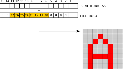
The low order byte and the high order byte of the 16 bit address needs to be sent to the data port. The address is the logical offset from the start of the tile bitmap area.
        LD    A,06H
        OUT  (40H),A
        LD    A,00H    ; Low order byte
        OUT  (41H),A
        LD    A,00H    ; High order byte
        OUT  (41H),A
07H - Set sprites bitmap pointer
Sets the logical address of the bitmap area used to draw sprites on screen. Sprite tile index 0 is located at that memory address, tile index 1 is located 64 bytes after, etc. each tile is 64 bytes.
The low order byte and the high order byte of the 16 bit address needs to be sent to the data port. The address is the logical offset from the start of the tile bitmap area.
        LD    A,07H
        OUT  (40H),A
        LD    A,00H    ; Low order byte
        OUT  (41H),A
        LD    A,00H    ; High order byte
        OUT  (41H),A
0CH - Write to sprites data area
Starts writing to the sprites data area. Each sprite is composed of 4 bytes that defines the x and y position, the tile index to draw, the size and other flags.
The first byte sent to the data port is the sprite index to write, with 00H as the first sprite and 1FH as the last (up to 32 sprites can be displayed on screen). Subsequent bytes are the sprite definition bytes.
![]()
        LD    A,0CH
        OUT  (40H),A
        LD    A,00H    ; First sprite index
        OUT  (41H),A

        LD    A,00H    ; X
        OUT  (41H),A
        LD    A,00H    ; Y
        OUT  (41H),A
        LD    A,00H    ; Tile index
        OUT  (41H),A
        LD    A,00H    ; Flags
        OUT  (41H),A
The write pointer automatically increments with each write so it is not necessary to send a new command to update all sprites. The pointer wraps to the first index position after the last byte of the last sprite is written.
0DH - Write to tiles map area
Starts writing to the on screen tile map area.
The first two bytes sent to the data port are the low order and high order bytes of a 16 bit address offset from the beginning of the tile map area, with 0000H corresponding to the top-left tile and 04AFH corresponding to the bottom-right tile. Subsequent bytes are the tile indexes to display on screen.
        LD    A,0DH
        OUT  (40H),A
        LD    A,00H    ; Low order byte
        OUT  (41H),A
        LD    A,00H    ; High order byte
        OUT  (41H),A

        LD    A,01H    ; Tile indexes
        OUT  (41H),A
        LD    A,02H
        OUT  (41H),A
The write pointer automatically increments after each write and wraps to the beginning after the last tile index is written.
0EH - Write to tiles bitmap area
Starts writing to the memory area that holds the bitmap data of each tile or sprite. Bitmaps are 8x8 bytes so each tile takes 64 bytes of memory. The bitmap memory are can hold up to 480 tiles.
The first two bytes sent to the data port are the low order and high order bytes of a 16 bit address offset from the beginning of the tiles bitmap area, with 0000H corresponding to tile index 0, 0040H to tile index 1, etc.
        LD    A,0EH
        OUT  (40H),A
        LD    A,00H    ; Low order byte
        OUT  (41H),A
        LD    A,00H    ; High order byte
        OUT  (41H),A

        LD    A,C0H    ; RGB colors
        OUT  (41H),A
        LD    A,30H
        OUT  (41H),A
The write pointer automatically increments after each write and wraps to the beginning after the last pixel of the last bitmap is written.
The actual index pointers can be set with commands 06H for tiles and 07H for sprites.
The following commands can be used when bitmap modes are selected.
01H - Set pixel
Draw a single pixel on screen given the x and y coordinates and the color index. The command requires 3 bytes on the data port for each pixel to display.
        LD    A,01H
        OUT  (40H),A
        LD    A,00H    ; Y coordinate
        OUT  (41H),A
        LD    A,00H    ; X coordinate
        OUT  (41H),A
        LD    A,07H    ; Color index
        OUT  (41H),A
To allow X coordinates to reach the full range of horizontal pixels when in 320 pixels mode, bit 7 of the color index byte is also used as the 9th bit of the X coordinate value:
        LD    A,01H
        OUT  (40H),A
        LD    A,00H    ; Y coordinate
        OUT  (41H),A
        LD    A,00H    ; X coordinate
        OUT  (41H),A
        LD    A,87H    ; Color index + 8th bit of X coordinate
        OUT  (41H),A
The command remains active until a different command is sent.
09H - Clear screen
Clear the whole screen with color index 0.
        LD    A,09H
        OUT  (40H),A
0BH - Write palette
Writes to the colors palette.
The first byte sent to the data port is the color index to write in the range 0-7 for 3bpp modes and 0-15 for 4bpp modes. Subsequent bytes are the RGB color values to write to the palette.
        LD    A,0BH
        OUT  (40H),A
        LD    A,00H    ; First color index
        OUT  (41H),A
        LD    A,F0H    ; RGB color
        OUT  (41H),A
The color index is automatically increment after each RGB value is written and wraps after the highest allowed index is written.
0DH - Raw bitmap write
Starts writing to the raw bitmap video ram area.
The first two bytes sent to the data port are the low order and high order bytes of a 16 bit address offset from the beginning of the bitmap area.
        LD    A,0DH
        OUT  (40H),A
        LD    A,00H    ; Low order byte
        OUT  (41H),A
        LD    A,00H    ; High order byte
        OUT  (41H),A

        LD    A,01H    ; Pixel index values
        OUT  (41H),A
        LD    A,02H
        OUT  (41H),A
The raw bitmap area organization depends on the selected video mode.
With the 320x240 3bpp mode a group of 5 consecutive pixels are packed in a 16-bit word starting from bit 0.
![]()
When writing to the raw bitmap area the LSB must be sent first, followed by the MSB. Bit 15 must be set to 0.
With the 256x192 and 256x224 4bpp modes each byte specify the index value of 2 consecutive pixels.
![]()
The write pointer automatically increments after each write and wraps to the beginning after the last tile index is written.
Port 43H is used to synchronize the program execution to the display frame frequency. Writing to this I/O port (any value) causes the WAIT line of the Z80 processor to be pulled low to pause the program execution until the end of the current frame, then it is released and the program execution is resumed.
OUT (43H),A