This is the driver of ESP8266 for the Timed Laser Gun project (here the WebInterface), a remix of Remotely controlled torch robot by JJRobots. Timed Laser Gun project is an automatic toy to let you cat play with laser pointer. I used an ESP to control the servo motors and a RTC to provide a correct timing to schedule the events.
To programm the ESP, use the Arduino IDE, then follow this step :
- Go on File > Preferences, and change the URL of Board Manager with "http://arduino.esp8266.com/package_esp8266com_index.json", then click OK
- Now go on Tools > Board:Arduino one > Board Managers
- Search For "esp8266" and Click Install ( it will take a while )
- After installation go back on Tools > Board:Arduino one and click on "NodeMCU 0.9 (ESP-12E Module)"
- Now you can connect it and lunch the Load process
The hardware part is made by :
- x1 ESP8266 NodeMCU
- x2 Servo motor 9g
- x1 RTC
I used an RTC, to have a real timinig and schedule the event, but you can also use a Virtual RTC to simulate the timer ( obviously it will not be precise like RTC but you can every day sync with a remote server and it will be enough ).
Here the class I wrote and here how to use it :
void setup(){
  //String TimeNow = YourCustomTimeService.getStringTime(); // this in case you have a service that provide this string date format dd/mm/yyyy HH:mm:ss
  String TimeNow = "dd/mm/yyyy HH:mm:ss";
  String d =  TimeNow.substring(0,2);
  String h =  TimeNow.substring(3,5);
  String m =  TimeNow.substring(6,8);
  String s =  TimeNow.substring(9,11);
  rtc_timer = Rtc();
  rtc_timer.setup(d.toInt(), h.toInt(),m.toInt(),s.toInt());
}
void loop() {
  rtc_timer.loopTime();
  int seconds = rtc_timer.getSeconds();
  int minutes = rtc_timer.getMinutes();
  int hours = rtc_timer.getHours();
  int days = rtc_timer.getDays();
  // here you will use it
}
I removed the soldered pins just to save space, but I think you can do it without desoldering, just force a little bit. Use this ( I not if is ugly I'm not a painter :D ) datasheet to build the hardware, I just make a simple list of connection points:
- GND -> GND
- Vcc -> Vcc ( +5 )
- Sign -> D6
- GND -> GND
- Vcc -> Vcc ( +5 )
- Sign -> D5
- GND -> GND
- Vcc -> Vcc ( +3 )
- SDA -> D2
- SCL -> D1
(do not plug microUSB and connect battery simultaneously, I didn't try but I suggest to do not try)
- Positive -> Vcc ( +5 )
- Negative -> GND
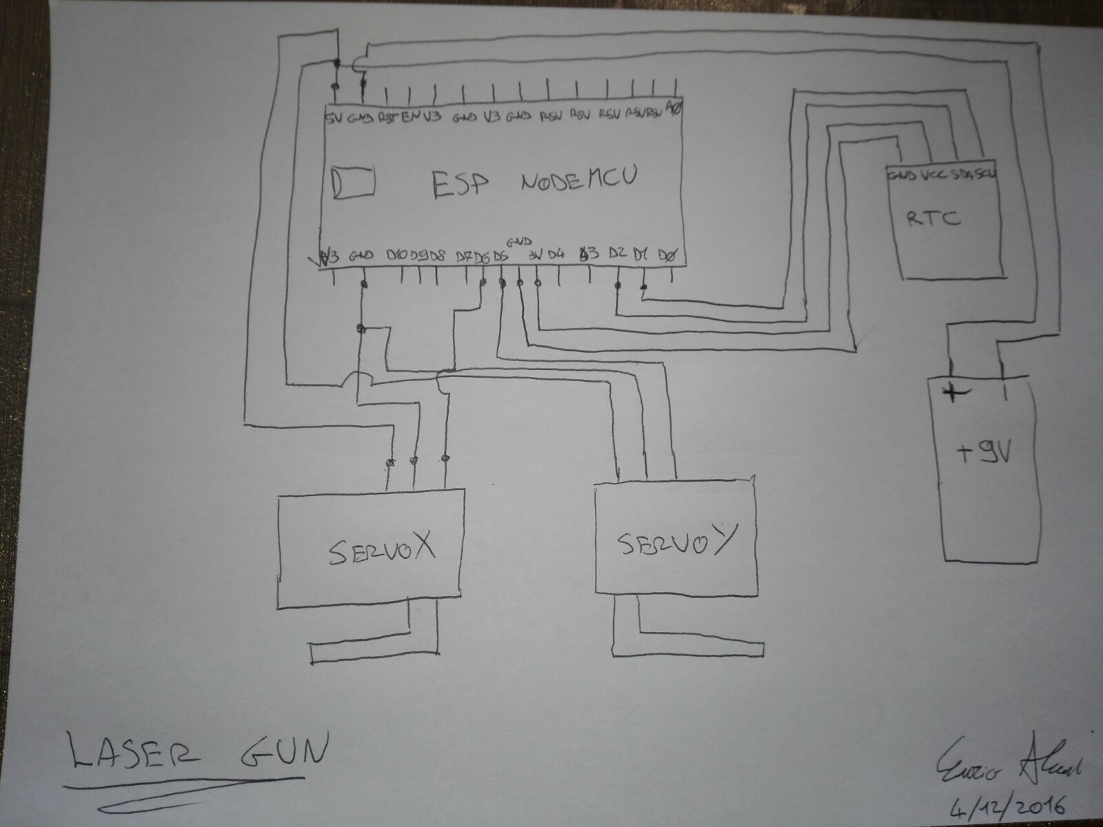
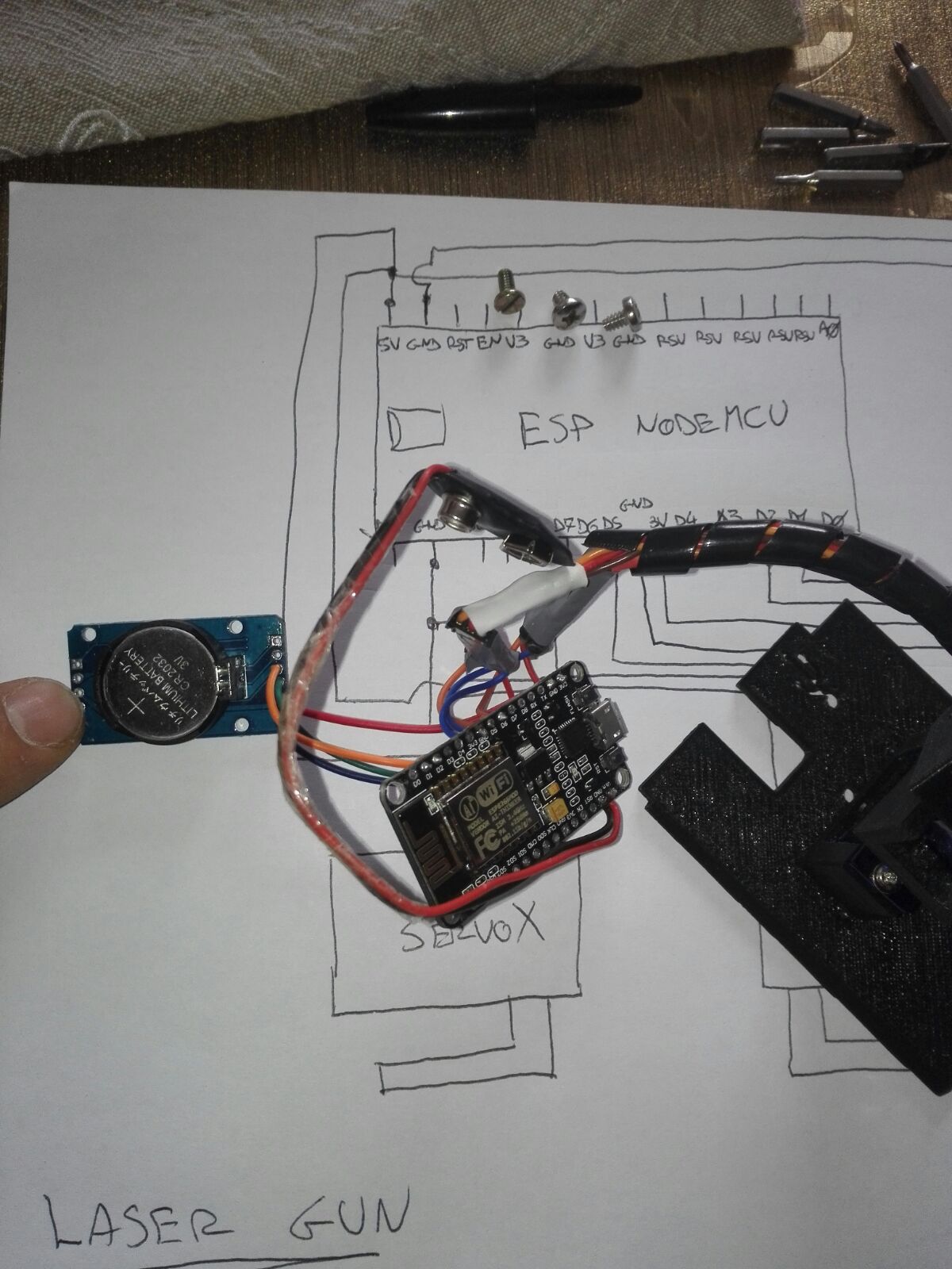
Then put all in the base case, use 2/3 mm screws ( I'm not sure ) to fix the ESP to the base, and that's it, program it and enjoy it.
For the information about the functionality of ESP, refer the WebInterface documentation