Currently working:
- Build instructions
- Running under emulation and on Pi 3 hardware
- Debugging under emulation and on Pi 3 hardware
- Frame buffer graphics
- FORTH repl
Currently not working:
- USB
- SD Card
- eMMC
- Network
Before the days of multitasking operating systems and graphical user interfaces, the experience of using a microcomputer was simpler and more immediate. You plugged in a monitor, plugged in the computer, and as soon as you flipped the switch you had an interactive environment. The machine was at your command. You could write a program, play a game, or just poke around with the hardware.
This project attempts to reproduce that experience. Instantly on and immediately interactive.
This is a bare-metal operating system. It runs directly on Raspberry Pi hardware, without the need for u-boot or Linux. There is a small kernel that initializes the device and starts a FORTH interpreter. Using that interpreter, you have complete control over the device. There is no memory protection, no process isolation, and very little fault recovery.
At the moment, the kernel does not have USB support so you will need to interact with the Pi via a serial console. See below for instructions on how to wire it up.
Eventually, there will be ready-to-run SD card images. For now, some assembly is required.
Currently supports Raspberry Pi 3b only.
You will need a GNU CC cross-compilation toolchain for aarch64.
On Linux, the Crosstool-NG project is a good way to get up and running.
On macOS, you can use Homebrew to install aarch64-elf-gcc and aarch64-elf-binutils.
Get the firmware binaries from https://github.com/raspberrypi/firmware
$ make download_firmware
Install https://github.com/tio/tio
If you're cross-compiling, type:
$ make clean all
Next, copy the firmware and kernel to a blank FAT32-formatted SD card, for example:
$ cp firmware/* /media/<SD-card>/
$ cp kernel8.img /media/<SD-card>/
$ cp sdfiles/config.txt /media/<SD-card>/
Put the prepared SD card into the RPi, connect the USB-to-Serial cable (see RPi Serial Connection for more details), and power-up to the console.
To get to the console, you'll need to connect:
$ tio /dev/ttyUSB0
Where <device> is something like /dev/ttyUSB0 or similar (wherever
you plugged in your USB-to-Serial cable). tio should be available
from your package manager of choice.
ARM systems have great support for in-circuit debugging. We can use GPIO pins to connect to the UART console as well as the JTAG debugging port. The downside is that this requires two different USB connectors to the host machine.
If you don't have a spare monitor for the RPi, you can also use an HDMI capture card to display the video in a window on your host machine.
       ┌────────────┐              ┌────────────┐
       │            │              │            │
       │      Host  │              │ RPi        │
       │            │              │            │
       │       USB 1│◄────────────►│ UART pins  │
       │            │              │            │
       │       USB 2│◄────────────►│ JTAG pins  │
       │            │              │            │
       │            │  ┌────────┐  │            │
       │            │  │HDMI    │  │            │
       │       USB 3│◄─┤Capture │◄─┤ HDMI       │
       │            │  │        │  │            │
       │            │  └────────┘  │            │
       │            │              │            │
       └────────────┘              └────────────┘
UART is serial. USB is serial. All good, right? Well, no. The protocol is wrong and the voltages are wrong. RPi GPIO uses 3.3v signals. That will look like a floating pin to USB. Worse, USB will feed +5v to GPIO which could damage your device.
Generic USB-to-TTL cables seem to work OK. Here is how to make the connections:
USB-to-TTL    RPi board      GPIO pin
label         header pin     (aka Broadcom pin)
----------    ----------     ------------------
3v3           Not connected
TXD           10             GPIO 15 / RXD1
RXD           8              GPIO 14 / TXD1
GND           6, 34, 39 or 9 -
+5V           Not connected
We need a common ground but do not want to supply power via this cable.
Some tutorials recommend the FTDI C232HM DDHSL-0. I was unable to get this to work.
I have used the Olimex ARM-USB-TINY-H rev. C successfully.
See the ARM-USB-TINY-H's JTAG pinout for reference.
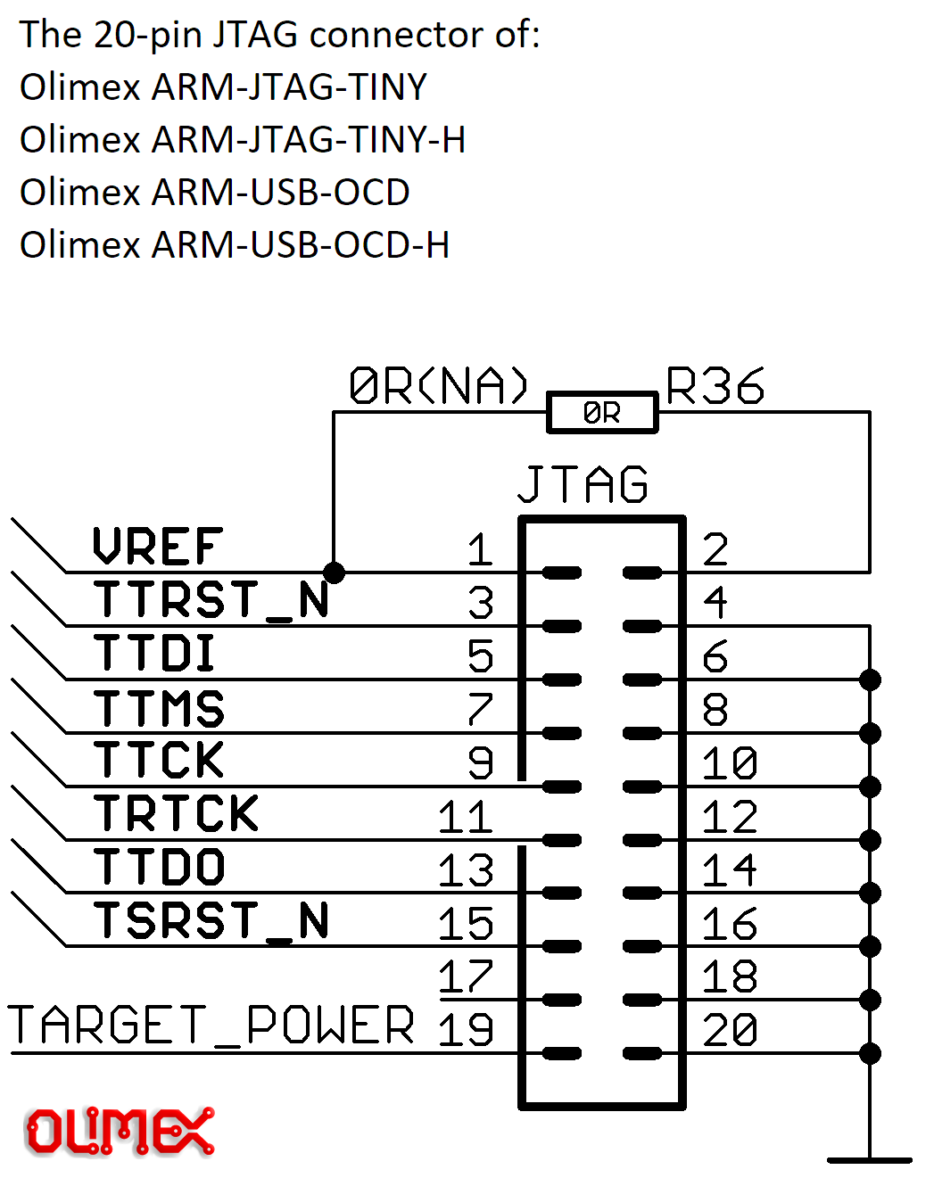
Function   Olimex pin    Broadcom       Physical board
                         GPIO pin       pin number
--------   ----------    ----------     ------------------
Vref       1                            1
GND        4                            9
TRST       3  (blu)      22             15
TDI        5  (grn)      26             37
TMS        7  (yel)      27             13
TCK        9  (ora)      25             22
RTCK       11 (red)      23             16
TDO        13 (brn)      24             18
Note that we again create a common ground. In this case we also need
to connect Vref.
It's probably a bad idea to run the JTAG and UART USB cables to different host computers.
To enable JTAG debugging, add the following line to the config.txt
on the SD card you will boot the RPi from:
enable_jtag_gpio=1
Note that this will make the RPi wait for a JTAG connection at boot time. It will not boot normally without the debugger.
If we just run with the regular SD card, then by the time we start up OpenOCD on the host (more about that shortly) all the interesting kernel startup work has already finished. We need a way to buy some time to set up all the connections.
The solution is to boot from a tiny image that puts the RPi core into a spinloop. The image consists of a single branch instruction, PC-relative, with an offset of zero. The CPU will spin on this instruction, while we run OpenOCD and get everything connected.
To create this image, run make sdfiles/infloop.bin.
To use this image, copy it to your boot SD card as kernel8.img.
Then, after connecting with make openocd_gdb as described in the
next section, load the real kernel by running load at the GDB
prompt.
Another rats' nest of connections, I'm afraid:
- GDB for control of debugging. It connects to OpenOCD
- OpenOCD using the USB-to-JTAG connection to talk to the chip.
- tio as a modem emulator, using the serial device from the to the USB-to-TTL connection. (On Linux this is /dev/ttyUSB0).
- If capturing video, a display program on the host. On Linux, guvcview or OBS both work. OBS is known to work on macOS hosts.
 ┌────────────────────────────────────┐              ┌────────────┐
 │                                    │              │            │
 │                               Host │              │ RPi        │
 │                                    │              │            │
 │                   tio ◄─────► USB 1│◄────────────►│ UART pins  │
 │                                    │              │            │
 │   GDB ◄─────► OpenOCD ◄─────► USB 2│◄────────────►│ JTAG pins  │
 │                                    │              │            │
 │                                    │  ┌────────┐  │            │
 │                                    │  │HDMI    │  │            │
 │              guvcview ◄─────► USB 3│◄─┤Capture │◄─┤ HDMI       │
 │                                    │  │        │  │            │
 │                                    │  └────────┘  │            │
 │                                    │              │            │
 └────────────────────────────────────┘              └────────────┘
To get this running requires three terminal windows (or tmux panes) on the host:
- Start tio:
tio /dev/ttyUSB0 - Start OpenOCD:
./tools/openocd.sh - Start gdb:
make openocd_gdb
(Note to self: I should add targets to the Makefile for steps 1 and 2)
If everything has worked, gdb will be able to inspect registers, step through code, and even intercept exceptions.
You can install the QEMU ARM support package, then run:
make emulate
This will start qemu-system-aarch64 emulating a Raspberry Pi model 3b
with its serial I/O connected to your terminal's stdin/stdout.
You can use the Crosstool-built version of GDB to debug the QEMU-hosted binary. In one terminal window, run:
$ make debug_emulate
This will tell QEMU to allow GDB remote debugging, and to wait until the debugger is attached before running the software. To attach GDB, in another terminal, run:
$ make gdb
(gdb) target remote localhost:1234
(gdb) layout split
(gdb) break _start
(gdb) continue
Use stepi (or si for short) to step by assembly instruction or
step to step by source line.
If you want to use the emmc-/sdcard- forth commands in the emulator then you need to specify a path to an MBR-formatted disk image when you run make. For example:
make SDIMAGE=../ros/2023-12-05-raspios-bookworm-armhf.img
If all has gone well, you should have a prompt that looks like:
>