This document provides an overview of how to get Trad Rack running. Each section should be completed before moving on to the next.
Table of Contents
- BOM/sourcing and other required hardware
- Printing required parts
- Mechanical assembly
- Wiring
- Klipper installation
- Servo calibration
- Selector calibration
- Slicing
- Changing Slicer_Unload macro settings
- First load and unload
- Further reading
The bill of materials/sourcing guide for Trad Rack can be found here.
Before placing any orders for parts for Trad Rack, it is recommended to read the Printer and hardware requirements document in case there are any other items you may want to combine into your orders.
See the following files/folders:
- Print Settings and File Key: print settings to use and info on reading the STL filenames.
- STLs folder: contains all STL files.
- STLs README: information on what parts to print.
See the build instructions for guidance on assembling Trad Rack.
Tip
An eDrawing is also available if you want to view a 3D model of Trad Rack. You will need eDrawings Viewer to open this file. If you are using the Nebula control board, a separate eDrawing is also available for help on assembling its enclosure.
See the Wiring document.
See the Klipper installation document.
This section involves setting the rotation direction and angles of the servo. You will need to have Trad Rack fully assembled, wired, and connected to your printer with Klipper running.
To prepare, remove the servo from Trad Rack by undoing the 2 screws that attach it to the right carriage.
Run the following gcode command:
TR_SERVO_UP
Then run the following gcode command, and this time observe the motion of the servo. When viewed from the front of the servo spline, the servo should rotate clockwise:
TR_SERVO_DOWN FORCE=1
If the servo rotated clockwise, you can continue on to setting the
servo horn angle. Otherwise, in your Klipper
config, swap the values of servo_down_angle and servo_up_angle in
the [trad_rack] section. Then restart Klipper and continue.
Run the following gcode command:
TR_SERVO_DOWN FORCE=1
Loosen the screw in the center of the servo horn and the screw in the clamp.
For this section, you will need the servo jig that has "HORN ANGLE" written on the side:

Insert the servo into the servo jig. You may need to rotate the servo horn around the servo spline by hand so that it is at the correct angle for the bearing to fit into the jig. The servo's wires should be exiting to the left to match the orientation in the image:

Tighten the two screws you loosened earlier. Then remove the servo jig.
For this section, you will need the servo jig that has "UP ANGLE" written on the side:
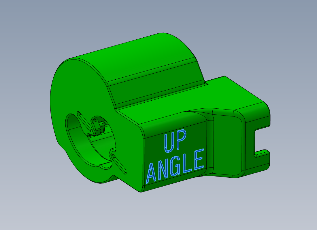
Insert the servo into the servo jig. The servo's wires should be exiting to the left to match the orientation in the image:

Run the following gcode command. Observe the "commanded angle" that is reported in the console:
TR_SERVO_TEST
Look at the front of the servo jig and check the position of the screw in the bearing relative to the slots. The goal of this section is to get the screw close to lining up with the slots:

There is a range of acceptable angles, and the screw does not have to exactly align with the slots. If the servo angle is within the target range, the jig will be able to slide far enough over the servo that the screw protrudes from the front of the jig:
| Wrong angle (screw can't protrude) | Angle within target range (screw protrudes) |
|---|---|
 |
 |
If the jig is blocked from being able to slide far enough for the screw to protrude, you will need to try another angle. Use the following command to test a specific angle. The "commanded angle" from earlier corresponds to the current angle of the servo. A higher angle will turn the servo counterclockwise, and a lower angle will turn it clockwise:
TR_SERVO_TEST ANGLE=<angle>
Repeat with different angles as necessary until the servo is within the target range.
Once the servo aligns well enough with the slots that the screw can
protrude from the jig, observe the last "raw angle" value reported in
the console. In your main Trad Rack config file, replace the value of
servo_up_angle in the [trad_rack] section with the "raw angle"
value. Remove the servo jig and restart Klipper. Then run the
following gcode command:
TR_SERVO_DOWN FORCE=1
Finally, reattach the servo to Trad Rack.
This section involves calibrating lane_spacing, as well as the min,
endstop, and max positions of the selector motor. You will need access
to filament (either a spool or a short piece is fine).
Run the following gcode command and follow the instructions in the console:
TR_CALIBRATE_SELECTOR
When the calibration finishes and you are prompted to do so, replace the values in your main Trad Rack config file with the new values for the following:
- in [trad_rack]:
lane_spacing
- in [stepper_tr_selector]:
position_minposition_endstopposition_max
See the Slicing document.
This section involves adjusting the settings of the Slicer_Unload macro to match your slicer settings so that toolhead unloads performed outside of a print will closely match toolhead unloads performed during a print.
Under [gcode_macro Slicer_Unload] in your copy of
trad_rack_optional.cfg,
change the values of the following variables to match the values you
set in the slicer profile. Variable names match the "parameter names"
used in the slicer config files:
- all variables under the comment
# printer settings - all variables under the comment
# filament settings
In addition, if you are using SuperSlicer, do the same for all
variables under the comment # filament settings only in SuperSlicer.
Set variable_superslicer to True if you are using SuperSlicer. If
you are using PrusaSlicer or OrcaSlicer, set it to False.
Optional: if you want to use different tip-shaping settings for
different filaments (when unloading the toolhead outside of a print),
you can define presets in [gcode_macro Set_Slicer_Unload_Preset] in
the same file. See the comments in the macro and the example preset
variables for reference.
This section goes through the process of running your first toolhead load and unload to test Trad Rack.
Run the following command to home Trad Rack's selector:
TR_HOME
Get a filament spool ready to feed into Trad Rack. Then run the following command, and insert the filament into lane module 0 when prompted to do so in the console:
TR_LOAD_LANE LANE=0
Trad Rack should now have a filament loaded into lane module 0.
To load the toolhead from tool 0 (which starts with lane 0 as its default lane*), run the following command:
T0
* see the Gcode reference document
for more details on the available parameters for the TR_LOAD_TOOLHEAD
and T<tool index> toolchange commands.
Depending on your hotend_load_length value, filament may or may not
come out of the nozzle.1 For the sake of this test, run the
following commands to ensure filament comes out of the nozzle:
M83
G1 E10
Run the following command to unload the toolhead. Trad Rack should retract the filament back into lane module 0:
TR_UNLOAD_TOOLHEAD
Congrats, you have completed your first load and unload with Trad Rack!
When printing with Trad Rack, make sure to load all the filaments you
might need into their lane modules beforehand using the TR_LOAD_LANE
command (after ensuring Trad Rack's selector is homed using TR_HOME
as needed). It is also possible to load filaments into the lane
modules completely by hand without any gcode commands, but this is
generally not recommended since you will need to make sure the
filament tip is pushed far enough forward that Trad Rack can grab it
but not so far that it blocks selector movement.
It is up to you whether or not to load the first filament to the
toolhead (using T<tool index> or TR_LOAD_TOOLHEAD commands)
before starting a print. Either way works, as the start gcode in the
slicer will ensure that the first filament gets loaded if it isn't
already.
Whenever you need to unload filament from the toolhead, you can use
the TR_UNLOAD_TOOLHEAD command. If a filament is currently loaded
and you want to load a different one, you do not have to call
TR_UNLOAD_TOOLHEAD before calling a toolchange command (either
T<tool index> or TR_LOAD_TOOLHEAD) to load the next filament since
the toolchange command will automatically include the unload as
needed.
This marks the end of the required steps to get Trad Rack running. See the Overview document to see the full list of documents available. Some of these were already linked in this guide, but there are additional ones that provide more information on what values can be changed for fine tuning, what gcode commands are available, etc.
Footnotes
-
It is recommended to set
hotend_load_lengthto a value small enough that filament does not ooze out directly after calling the toolchange command so that you do not get a blob on the wipe tower. However, it should not be so small that there are large gaps in the wipe tower. ↩