This document provides information on wiring for Trad Rack.
Table of Contents
The selector harness and the selector stepper and endstop will need to be connected to the control board. This document does not cover connections to your control board since they will depend on the specific board you are using. If you are using one of the provided base config files, see the comments in the file for which pin/port to use for each signal. Check the manufacturer's documentation if you need help figuring out where each pin/port is located on the board.
It is recommended that you take into account your control board's location when cutting the cables for the selector harness and the selector stepper and endstop, but that you connect these cables to the control board after completing all the sections in this document.
This section covers wiring for Trad Rack's selector:

The selector harness goes from the control board, through the drag chain, and into the Microfit holder printed part on the selector. The Microfit plugs should be inserted into the front of the Microfit holder and will click into place. The harness should be zip-tied to the right carriage printed part at the location marked in red.
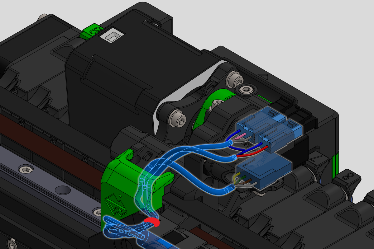
The length of cable between each plug and the near drag chain end should be about 120-140mm.1 The overall length of the cable will also depend on the length of your drag chain and the distance between the fixed end of the drag chain and your control board.
If you are using an 8-conductor cable, you will need to split the GND wire into 2 separate wires to go into both the 3-pin Microfit plug and the 2-pin one. This can be done by splicing wires together with a solder joint. Wiring info is shown below:
| Wire | Color | From | From pin | To | To pin |
|---|---|---|---|---|---|
| Motor A | White | Drag chain cable | 1 | 4-pin Microfit plug | 1 |
| Motor C | Brown | Drag chain cable | 2 | 4-pin Microfit plug | 2 |
| Motor B | Green | Drag chain cable | 3 | 4-pin Microfit plug | 3 |
| Motor D | Yellow | Drag chain cable | 4 | 4-pin Microfit plug | 4 |
| Servo signal | Gray | Drag chain cable | 5 | 3-pin Microfit plug | 3 |
| 5V | Pink | Drag chain cable | 6 | 3-pin Microfit plug | 2 |
| GND | Blue | Drag chain cable | 7 | 3-pin, 2-pin Microfit plugs | 1, 1 |
| Filament sensor signal | Red | Drag chain cable | 8 | 2-pin Microfit plug | 2 |
The servo cable goes from the servo to the matching plug in the Microfit holder. You will need to cut the existing cable to length and attach a 3-pin Microfit receptacle.

It is recommended to loop the servo cable around the servo as shown above to leave some extra length in case of future changes. The length of the cable should be about 170mm.1 Wiring info is shown below:
| Wire | Color | From | From pin | To | To pin |
|---|---|---|---|---|---|
| GND | Black | Servo | N/A | 3-pin Microfit receptacle | 1 |
| 5V | Red | Servo | N/A | 3-pin Microfit receptacle | 2 |
| Servo signal | White | Servo | N/A | 3-pin Microfit receptacle | 3 |
The stepper cable goes from the filament driver stepper motor to the matching plug in the Microfit holder. You will need to cut the existing cable to length and attach a 4-pin Microfit receptacle.
The cable should be zip-tied to the motor plate and middle carriage printed parts at the locations marked in red. Make sure there is enough slack between these two ziptie points so that the cable is not stretched when the motor pivots to lower the drive gear.

The length of the cable should be about 210mm.1 Wiring info is shown below:
| Wire | Color | From | From pin | To | To pin |
|---|---|---|---|---|---|
| Motor A | Black | Stepper | N/A2 | 3-pin Microfit receptacle | 1 |
| Motor C | Green | Stepper | N/A2 | 3-pin Microfit receptacle | 2 |
| Motor B | Red | Stepper | N/A2 | 3-pin Microfit receptacle | 3 |
| Motor D | Blue | Stepper | N/A2 | 3-pin Microfit receptacle | 4 |
The filament sensor cable goes from the filament sensor microswitch to the matching plug in the Microfit holder. To make the cable, solder 2 wires to the outer pins of the microswitch and attach the other ends of the wires to a 2-pin Microfit receptacle. The cable should be zip-tied to the Microfit holder at the location marked in red.

The length of the cable should be about 155mm.1 Wiring info is shown below. It does not matter which of the 2 wires goes to which pin in the Microfit receptacle:
| Wire | Color | From | From pin | To | To pin |
|---|---|---|---|---|---|
| GND | Black | D2F-L microswitch | COM | 2-pin Microfit receptacle | 1 |
| Filament sensor signal | White | D2F-L microswitch | NC | 2-pin Microfit receptacle | 2 |
The selector endstop cable goes from the endstop microswitch to the control board. To make the cable, solder 2 wires to the outer pins of the microswitch (and terminate the opposite ends of the wires as necessary to connect to your control board).
The stepper cable goes from the selector stepper motor to the control board.
The cables should be zip-tied to the lower motor mount printed part at the locations marked in red.

Footnotes
-
It is recommended to do a test fit before cutting any wires. ↩ ↩2 ↩3 ↩4
-
If your stepper has a detachable cable and you do not already have a premade cable that matches the colors in this table, refer to the stepper's datasheet for which pin on the stepper's connector corresponds to which wire/coil. The wires
Motor AandMotor Cconnect to one coil, andMotor BandMotor Dconnect to the other. ↩ ↩2 ↩3 ↩4