Home
Welcome to the HardwareSerialRS485 wiki!
Work in progress ...
Michael Jonker
This project provides a software suite to support the use of an RS485 transceiver connected to the USART (Tx/Rx pins) in a half-duplex, concurrent multi-drop (i.e. multi-master, multi-slave) environment. For this purpose, the software suite provides capabilities for message addressing and filtering as well as collision detection and collision avoidance.
Project page: https://github.com/MichaelJonker/HardwareSerialRS485
An example of a hardware connection is given in Figure 1, which shows the connection of the RO, DI, RE* and DE lines of an RS485 transceiver to the Atmega/Arduino. Connecting the enable lines DE and RE* to separate pins of the Atmega/Arduino, gives the software full control over the communication via RS485.
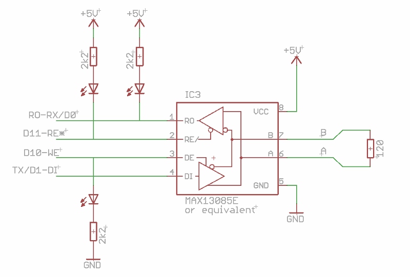
Figure 1.
The individual control of the RS485 enable lines allows for various modes of operation, such as collision detection (requiring read while write) or exclusive communication over RS232 (requiring disabled read, as enabling read from RS485 mutes the regular RS232 reception). Furthermore, the RE* pull-up circuit ensures that the RS485 read is disabled upon reset of the Atmega/Arduino, hence allowing program downloads in the usual way from the Arduino IDE. Note that, apart from the RE* pull up resistor, all other extra components in the above diagram are optional. However, the presence of the LEDs to indicate the receive/transmit status of the RS485 will, be very appreciated for diagnostics.
The RS485 circuit can be implemented on a breadboard (Figure 2), soldered onto a shield (Figure 3), or included into a new PCboard design (Figures 4).

Figure 2. The simplest breadboard realization of the circuit shown in figure 1, based on the Arduino/Micro and a directly mounted RS485 transmitter IC.
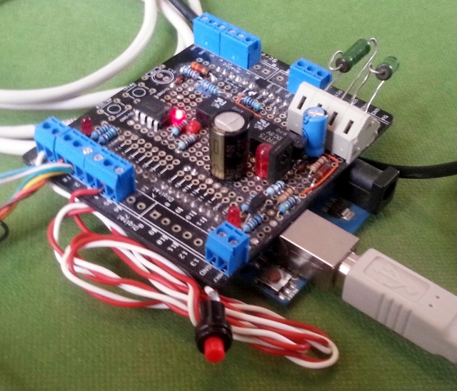
Figure 3. A more sophisticated implementation with additional circuitry based on the screw-shield. The RS485 interface IC is visible in the top-middle on the shield.
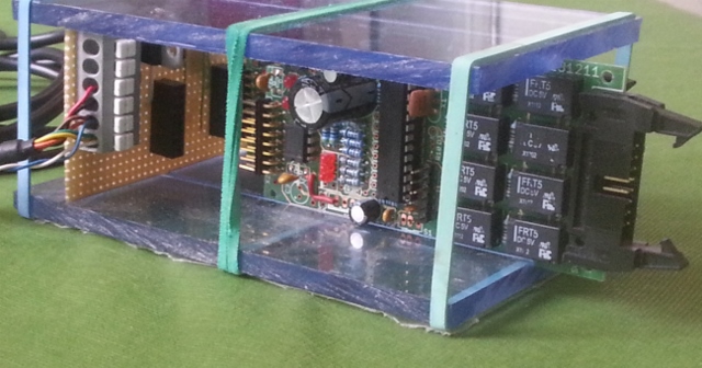
Figure 4. A prototype chassis with a primitive backplane connects two custom designed Atmega/Arduino PC boards to the RS485 bus.
Alternatively a circuit board containing a 485 interface can be procured from http://yourduino.com/sunshop2/index.php?l=product_detail&p=323 (see Figure 5). This board does not, however, contain the LEDs to indicate the status of the enable lines. More important, this board has a DE high pullup, (in contrast to the recommended configuration shown in figure 1), with the implication that upon start-up of the Arduino (all ports tri-stated), Data Transmission is enabled. As a consequence, the MAX485 will actively drive the RS485 bus, blocking any bus transmission. Hence, it is suggested to remove the DE pullup and to add an external pulldown resistor. Finally one should be aware that these interface boards contain a 120 ohm bus termination resistor, which is not a problem if used in point to point communications, but not in a multidrop environment, where only the extremities of the bus should be terminated.
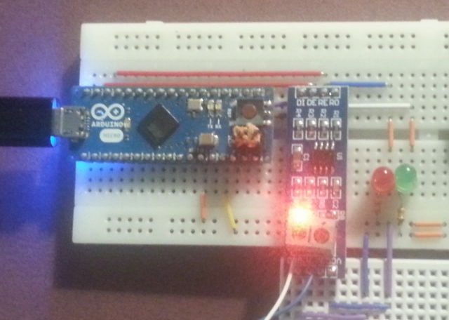
Figure 5. Breadboard version based on a small pc board with a premounted RS485 interface. Due to circuit failure in the RS485 PC boards (possibly following a manipulation error), this configuration was not fully tested.
Figure 6 shows the test setup used by the author to develop the HardwareSerialRS485 library, connecting together 6 RS485 devices (One RS485-USB connected to the PC, one Uno/ScrewShield, 50 m of cable, one Micro/breadboard, two custom boards, a second RS485-USB connected to the PC).
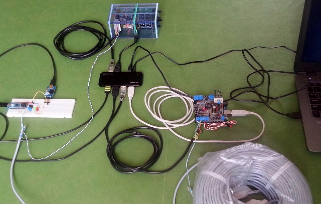
Figure 6.
The software is implemented on top of a rewritten HardwareSerial class that makes use of several included helper classes to extend its capabilities. This class is almost fully compatible with the classical HardwareSerial version provided by the Arduino distribution and hence methods like the Serial.print() can be used unchanged.
N.B., the qualifier 'almost' have been added in the previous sentence as the HardwareSerialRS485 class does not support internal buffers larger than 256 bytes. However, the need for a large buffers in a RS485 concurrent multi-drop environment has yet to be demonstrated.
RS485 capabilities are provided by the helper class RS485serial allowing one to switch between RS232 and various RS485 based operational modes (full details are given below).
-
Collision avoidance is implemented through the assignment of a message priority. A node will not start transmission before the bus has been idle for a time determined by the priority. Note that the highest priority is given to messages with the lowest priority number.
-
Collision detection is implemented by read-verified-write, i.e. all data written is checked on the fly for proper echo-back. If the software detects a frame error or a data mismatch when the echo character is received, it will disable the RS485 transmission and flag the collision status. The included transaction management will resend the message after the bus is idle again.
The helper class, MessageFilter, provides message recognition and address filtering at the interrupt level.
Due to a possible large data traffic between various nodes on the half duplex multi-drop RS485 bus, and given the limited capacity of the internal message buffer of the HardwareSerialRS485 class, there is a risk of message loss due to buffer flooding. This real-time filtering capability reduces this risk by pruning data not intended for the node, leaving the internal message buffer of the HardwareSerialRS485 class fully available for messages that are destined to the node.
It should be noted that message filtering in the presence of high bus occupancy will consume (real time) processing resources of the Atmega/Arduino. In a future version may, as an option, exploit the hardware addressing capabilities of the Atmega chip (see also future developments).
Finally, a helper class Transaction provides support for message oriented transmission. Under control of this class, a message that fails during transmission, (bus occupancy, collision) will be retried after idle conditions are met. A call to endTransaction() will, if needed wait until the message is transmitted (not including acknowledgment) and report to the caller on the completion status.
The project provides an example/demo sketch and instructions of usages.
A simple command response sketch RS485CommandResponse is included in the example folder under the HardwareSerialRS485. This primitive sketch allows for switching between various communication modes and implements some rudimentary commands for echo and information printing.
Host (PC or Android) connection to the RS485 bus can be achieved by an RS485 to USB converter. As an example, the RS485-USB converter from FTDIchip (FTDIchip Products USBRS485) was used for development by the author. Another possible candidate could be the Sparkfun BOB-09822 breakout board https://www.sparkfun.com/products/9822. However, these solutions will not provide host-based collision detection and only a limited capability of host based collision avoidance. A project for a USB RS485 interface (discussed below) may provide these facilities in a future release.
Various applications exist to communicate with the RS485 nodes on the bus. For simple command responds testing, a simple terminal emulator such as Putty (www.putty.org) or FTDI UART terminal can be sufficient. More complex applications must be developed explicitly. (In a future post, the development of an Android specific application will be published.