CAD for new filter flow channel design #6
Comments
|
Given that the overall width of the system is a real constraint (so that backwash works well) and given that the only reason for the trapezoidal center section is to help solve a failure mode that will hopefully not be a problem, and given that the flow area of the center section likely ends up being much larger than needed, I propose that the center section be turned into a rectangle. The cross sectional area of the center section can be estimated from manifold analysis. The orifices would presumably have a contracted velocity that corresponds to a head loss of about 5 cm. (head loss = v^2/(2g) where v is the contracted velocity which is also required for the manifold design. I'm guessing that if you revert to a simple rectangular cross section the design will be simpler, the alignment error will go away, and you will be able to design the width of the rectangle using the manifold equation. |
|
Hi, In general, I think that this misalignment does no matter. Our printer will barely see it at wall thickness of 2 mm. I'd say that you should work on spacing the holes and get this thing printed. Do you know how tall can we print on our 3D printer? Regarding the reason for the misalignment - it happens because the bottom wall thickness is measured at 90deg and the roof thickness at 60deg. There is no way they can be aligned. If you want it to look nicely, you should either extend the bottom of the roof or draw the geometry with single lines and convert them to the walls using Slot option (setting slot thickness to 2 mm). Let me know if that helps:) Br., |
Onshape File
The above linked document has the parametrizable CAD model for the 'tick' design of the flow channel.
The design is basically complete except for needing to add holes and a slight issue with the calculation of the height of the tick body in relation to the spacing of the gravity exclusion zones (referred to as 'legs' in the configurations).
The spacing between the gravity exclusion zones is set as : (sin(30 deg)/sin(#beta))*(#leg_length+#tick_leg_t), where 30 degrees is the angle of the 'legs' such that sand will slide down by itself, beta being the angles at the top of the body.
The diagonal length of the body is then defined by ((sin(30 deg)/sin(#beta))* (#leg_length-#tick_leg_t/(#leg_n-1))+#tick_leg_t)*(#leg_n-1)+#tick_leg_t
However, the bottom of the bottom leg does not line up with the bottom of the body, and we are unable to figure out where the math went wrong.
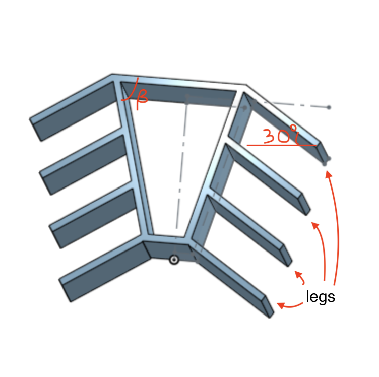
Above is a screenshot of the 'tick' with the terms we used in the configurations labeled (beta, legs, 30 degrees)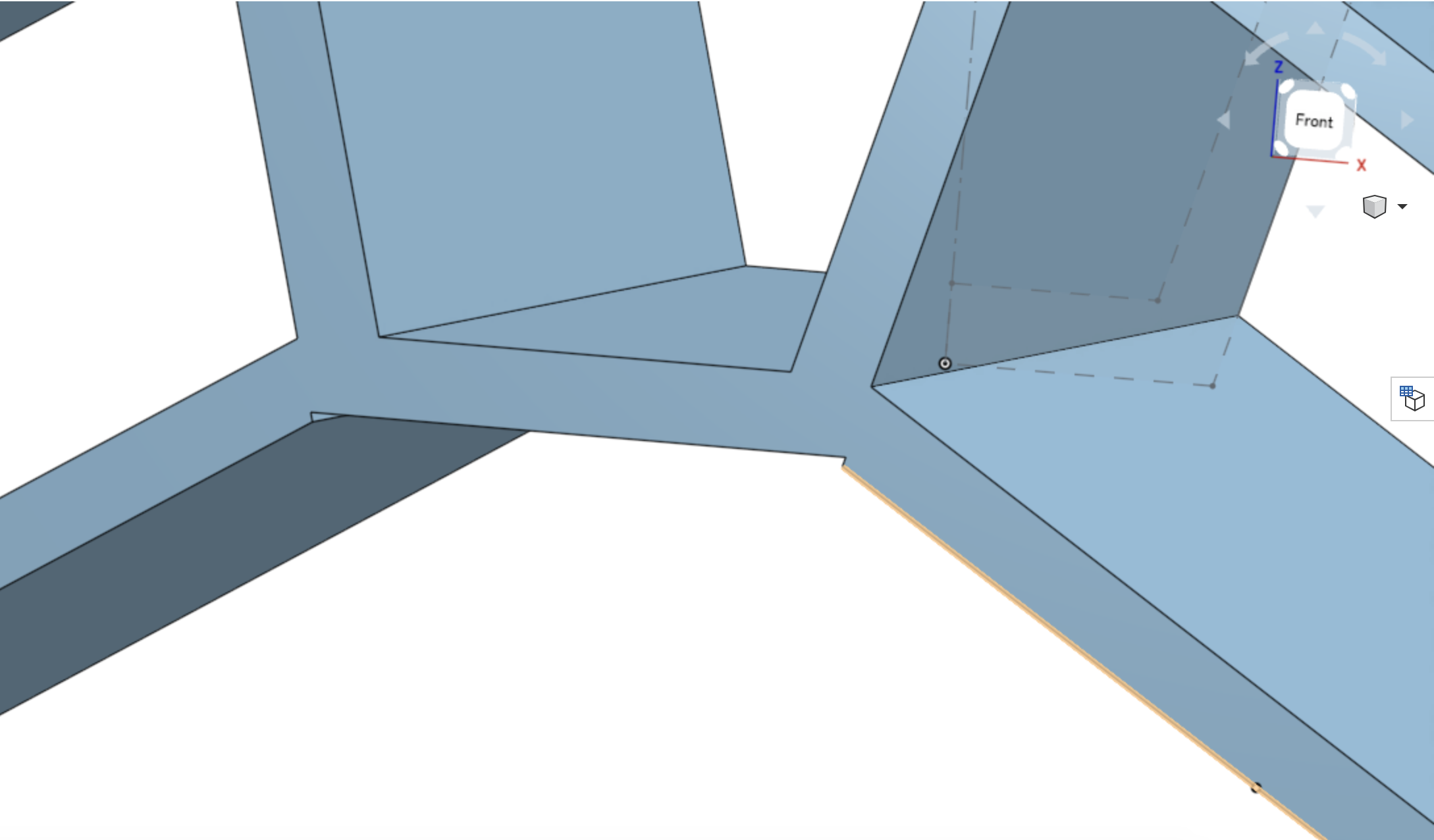
Above is the main issue with the CAD: the bottom leg and the bottom of the 'body' is not aligned.The text was updated successfully, but these errors were encountered: